
At this project’s inception, I was inspired to design and build an inexpensive RC plane that I could fly for enjoyment and perhaps in the future put a camera on. As an aspiring engineer, the idea of building something that could do something as tangible as sustained flight enthralled me. I’ve come a long way since this project- the plane did fly really well, so I wrote this build log for it.

 This plane is loosely based off of the Cessna 172 Lower Photo from (http://www.bing.com/images/search?q=cessna+172)
Specs:
48” Wingspan
30” long
Weight: 750g
Motor Thrust: 650g
Build Material: Housing Insulation foam
Long Flight times and [maybe] aerial video

Electronics are the most difficult part of this build. However, these parts are interchangeable with equivalent ratings (KV, amp draw, and voltage for motor, amp rating for esc, and capacity and discharge rate of the battery). This is all the stuff you’ll need to start flying.
Materials:
The Airframe:
The Fuselage: 1/2 inch DOW Housing Insulation foam, Pink Foam Insulation Sheeting, and EPP(Expanded PolyPropylene) foam are all names that I’ve heard this foam called. The local hardware store should carry this stuff. It comes in a 4’x8′ sheet that you can make about 1 and 1/2 planes out of. The foam is excellent for this application; it has good compression and impact strength (the latter is a must as you almost surely will slam this thing into the ground:D). It also is easy to sand, which is a must if you want the thing to look good.

4’x8′ foam sheet
The Wing:
The Wing is made out of the same sheet of DOW/Pink foam that the fuselage is made out of. It is a true airfoil wing. It’s very strong by itself, but you might want to add a wing spar. I would use a 1/4”(6 mm) wooden dowel from the local hardware store.
Rudder and Elevator:
Paper-backed foam board. Mine was laying around the house, but you can buy 20”x30” sheets for a dollar at the dollar store. The only reason that I picked this foam for the rudder and elevator was because I wanted the plane to look good, and I knew I could spray paint the paper without melting the foam. Note:You cannot spray paint Housing Insulation foam, nor can you use CA glue (superglue). The solvent will melt the foam.

Rudder and Elevator
Servo Push Rods for control surfaces:
I used wire coat hangers. They are inexpensive, work great, and can be replaced easily. I was being frugal; these were laying around the house. Other wire of sufficient strength will work also.

Coat hanger push rods
Electronics:
As I said earlier, this is where most of the money will be spent. The parts that I recommend are changeable as long as they have similar ratings and the motor and propeller setup provide enough power. I used a combination that was already put together for sale, but you can use any parts that have similar ratings.
Motor:
Lots of online sellers sell motors that can be substituted for what I used. As long as the motor and recommended prop pull current that your esc can handle, it should be fine. Thrust should be anywhere from 600-800 grams. Propeller should be around 10 inches with a light pitch (4.7 or 3.8), as this is a slow flying plane. Make sure it either comes with all the necessary hardware to mount to your plane and attach to your esc. These include connectors, heat shrink, a propeller mount and motor mounting hardware.

Brushless Motor
ESC:
Any esc that is rated around 20 to 30 % more than the max current draw of the motor will work. A much higher esc amp rating will work, but you can burn out your motor if you run full throttle too long.
Example: motor draws max 14.5 amps
Esc should be around 20 amp.
Servos:
You’ll need 3 for this plane, since it is a 4 channel.
They can be micro or standard. Micro are much lighter, but do the same job, so I used micro servos (9g servos)

Aileron servo mounted
Battery: I used a 3s 30c 2200mah, but up to 3000mah will work. It all depends on the flight time you want, but it should be a 3 cell (11.1v) and have a 30c or higher discharge rating. Remember that weight comes with higher capacity.
Charger: Read up on safe Lithium polymer battery charging, these batteries can be very dangerous and you must know everything there is to know before handling them.
Buy a balance smart charger that has a cutoff once the battery is fully charged. It is worth it.
Radio: There are very good transmitters out there for very cheap, but make sure it has at least 4 channels. Some name brands are overpriced, for what their radios do. Use your own judgement, but don’t buy junk.
With these materials, you can build a trainer 4 channel RC plane. The best part is that bad crashes aren’t expensive- a whole new plane doesn’t cost much; the electronics are reusable.
Optional landing gear: The great thing about metal landing gear is that it bends. I had all the parts to build my own, so I did that instead. I used PVC pipe split in half.
Wheels: be creative! Jar/container lids work well.

Building Materials:
These are tools you will need to build your plane.
-Sharp Hobby Knife and plenty of extra blades
-Hotwire cutter- There is a wealth of knowledge on the subject online. It is very easy to build your own. On this site is a build-along of a low power one.
-Meter stick, yard stick, or just a stick and a tape measure.
-Spray adhesive
-hot glue. Lots of it.
-sandpaper (preferably belt sander)
-Packing Tape
-Either Polycarbonate, Acrylic, MDF, Light plywood(3/16” or 3 ply)
-basic tool skills
The Fuselage:
The fuselage is our powerhouse and therefore the start of this build. Construction is simple- Cut out 7 side-profile templates, glue 5 together, cut out electronics bay, glue the last two, and sand.
Making templates:
Simply cut out 7 rectangles and use your hot wire (there are plenty of places online to learn how to make one) to cut out your desired shape. Mine is roughly modeled after a Cessna 172, but you can build whatever you want as long as you keep in mind weight and size. To help you if you’re not making the rough Cessna model I built, use pictures online. By messing around with 3 view drawings online, you can get a pretty good idea of what your plane should look like. A dimensioned drawing is below:

Templates from side and top view
I’ve included a dimensioned drawing of the side profile. These are for the plane that I’ve built, yours will be slightly different. Don’t be worried. Just because yours isn’t the same, it doesn’t mean that it won’t fly. Be creative if you want! I don’t know, build a flying banana or something.

Electronics bay, only for center templates
Cutting out templates:
Trace the shape in the pics below onto your pink foam sheet. It is dimensioned, but yours can be anything close. A bandsaw, scroll saw, or jigsaw would all work great for this. I used a simple hobby knife, which works equally well, but you are free to choose. Size them up against each other and make sure they are roughly equal. They can be off by about an inch, and you’ll be fine. Don’t be afraid to redo a template if it doesn’t match the others closely- remember, we need 7 total.
Gluing
Glue ONLY THE FIRST FIVE TEMPLATES together. You must glue only these so that you can cut out the electronics bay. To glue, lightly mist 3m spray adhesive (or Elmer’s spray adhesive, which I used) onto the foam. If you spray too close to the foam, it will melt while drying. Hold the can about 2 feet away and let it fall gently onto the foam. The stuff tacks quickly, so line them up and stick them together with time in mind. They should dry in about 30 minutes. Once this is done, you are ready to cut out the electronics bay.
Cutting out the electronics bay.
Now that you have a rough side profile with the first 5 sheets, you can cut out the electronics bay. Your battery should weigh anywhere from 170 to 240 grams, so this must be kept in mind for a proper center of gravity. Since the battery and motor must counterweight the rear of the fuselage, we will cut the compartment far forward. See the pictures below and the dimensioned drawing. It is a diagram of how your compartment should be. Most of the area on top where the wing will sit is cut out. USE COMMON SENSE. Do not cut out too much, and leave greater than 1/2” of foam at the bottom of the compartment. The foremost space is for the battery. Later, we will velcro it in place so that it doesn’t jiggle around during flight.
I did not take pictures of this step, but it will be clear after the 6th and 7th layers are added and I cut the profile and sanded. Use the pics.
Once you have cut out the compartment, you can glue the 6th and 7th templates on the left and right sides of the fuselage. Once this is done, you are ready to start shaping!!

After gluing
The Top Profile (Finally starting to look like a plane fuselage!)
This is where the fuselage becomes a fuselage. Once the last two layers are glued and have dried, you are ready to shape the fuselage. A drawing of the layers and top profile cut is shown below. I cut out all of the portions that stuck out, to make sanding a little less labor-intensive. If you have one, a broad coarse file will take care of most sanding, but a palm sander or belt sander will take care of sanding much faster. BE CAREFUL WITH SANDING. ALWAYS WEAR A MASK AND DO THIS IN A VENTILATED AREA. THIS STUFF IS DANGEROUS WHEN MELTED AND SANDED. I’ve included a picture of the main cuts you should make (with your bandsaw or hotwire). Sand every surface except the compartment, and you are ready for paper mache.
Paper Mache:
This is hardly a necessary step, but I wanted my plane to look good so I did it. If you are going to spray paint your plane, this is necessary. I covered mine, but I used a drywall paint to paint it. I chose a yellowish tan/brown paint scheme. If you want, you can even paint it after a picture you find online. Not only does the paper provide a paint-safe surface, but it also gives the foam immense rigidity that you cannot achieve any other way for an equivalent amount of added weight.

Paper mached
To cover your plane, you need newspaper or other thin paper (crepe paper works too), white craft glue (I used elemers), a paintbrush, and a bowl to make the mixture in. Pour about an 1/8th of a cup of glue and mix with an 1/8th cup of water. The mixture should be something like to one to one, but the exact ratio is not critical. Mix until it has a milk-like thickness. Add water or glue if necessary. Cut out long strips of newspaper. Apply the glue mix generously to a small part of the fuselage, and carefully lay a strip of newspaper on top. Apply glue with the brush on top of the newspaper. Do this to the entire plane, except the electronics bay. A picture of this step finished is included below.
Painting:
All I can say is that be weary of spray paint- it is very thin and the paper layers can show. I used drywall paint. Drywall paint will work if you skip the paper, and apply paint just to the foam. Heck, you can fly the plane as foam to if you don’t care to paint it. Understand that covering and painting the plane adds a lot of weight (about 4 oz with drywall paint)

Painted
With the fuselage done, you can move on to the elevator and rudder.

Tail section

- Rudder dimensioned drawing

From the original pink foam sheet cut out a long, unwarped piece that is 50” by 9”. Cut another strip 6” by 50”. Using the same gluing technique you used for the fuselage (Mist on the spray adhesive), Square up the 6” and 9” piece and glue them together. See the drawing below. This is your rough template. Now all that is left to do is sand it so that you have an airfoil. If the resources are available to you, seriously consider hotwire-cutting an airfoiled wing. You will be done much faster and the result will be more consistent, but you must build a rig to do this, and I didn’t have the necessary materials. Search online (use instructables, of course!) for a “hotwire Wing Cutter”. People make very clever rigs to do this, and their results look really good.If you cannot build a wing cutter, simply print out an airfoil template from an image search or other website. Use Word, Paint, or any other utility to size the wing chord (distance from leading edge to trailing edge of the wing) to 9”, because your wing is 9” long. Then, pin the template to the side of the foam wing and start sanding. Hand sanding takes a long time and is a lot of work, but my wing is proof that it can be done. A file or power sanding tool would be far more efficient. Take your time with this.

Airfoil…almost
With the finished Wing frame, you are ready to cut out control surfaces for the wings-the ailerons. You are also ready to embed the servo in the wing and attach controls. My ailerons are 1.5” by 12”. You can make yours bigger or smaller if you want more maneuverability. You can also play with the placement of the aileron arms to do this.
To attach these simply leave a 1/16” gap between the aileron and the wing and use packing tape. Some builders even cover the entire wing in tape. It is a little heavy, but it increases aerodynamics. The airflow over the wing is smoother. If you want to enhance this without adding too much weight, just cover the leading and trailing edge in packing tape.For the servo pocket, I simply marked and cut out the space with a hobby knife, but you can also heat up a screwdriver and burn an appropriate sized groove for the servo to fit in. DO THIS IN A WELL-VENTILATED AREA.The control rods are-you guessed it- coat hanger wire, and the linkage that attaches to the ailerons themselves are also coat hanger wire. The tube which holds the aileron arm is just a drinking straw. Check out the pictures to help you with this!!Once the servo and control linkage is embedded, only one thing remains; mounting. To mount the wing to the fuselage, use wood screws or other screws with a wide cut. I used three because that’s really all that are needed; one attaches near the front, where the cockpit would be if it were a real plane, and two go on the walls of the electronics bay. To secure these, I used pieces of layered cardstock (you can use any durable, hard card or cardboard) to help spread the clamping force of the screw. They serve as washers. You need to seat pieces of Acrylic, Polycarbonate, or light wood on the fuselage where the screws will attach to. I used polycarbonate because I had it laying around. These serve as places to anchor the screws. A picture below should help.

Attached to fuselage with screws
The numbers on your prob should be facing outwards.Plenty of great tutorials exist on the internet on how to solder connectors from battery, ESC, and motors- I will not go into the details.I’ve provided you with guidelines and described how I set up electronics, accompanied by pictures.Servos:
Start with Servos. I simply hot glued mine into the sides of the electronics bay. You can embed them in the foam, but this takes more time and potentially weakens the foam- I just glued mine because it was convenient.
 Servo Push Rods:
As I mentioned in the Materials step, I used a wire coat hanger for control rods. To make them look cleaner, I poked them through the back of the electronics bay. You can also embed the servos outside the electronics bay for easy access, but I wanted the plane to look cleaner. Start with a piece of wire about 25” long. Make sure it is straight. We will cut this down a few inches once they are situated, so you might need multiple hangers. First make a 90 degree bend at one end of the wire. The bended section will attach to your control horn on the rudder. Next, poke a hole through your fuselage, as shown in the picture. You can heat up the end of the hanger, and it melts as it pokes through, which is great because it provides a friction-free surface. You will do this step again for the elevator, but on the other side. Slide the wire through the hole (the straight end of course) and then affix the bent end to the control horn. Estimate the length of the bend you will make on the other side to attach the wire to the servo arm. Cut it to appropriate length, and you are done. Repeat for the elevator, making sure your bends are in the right directions.

Pushrods in through the electronics bay
Battery:
Battery setup is easy. All you need to do is put it in place and add a piece of velcro to both the fuselage and the battery. Use a piece larger than I did, and it will be secure.
Reciever: Velcro this also!! See the pictures.
ESC: Velcro this in place. Also, you’ll need to cut a hole where the battery connection end of this comes in and then out. It is important that you do this, because since the wing is screwed on it is inconvenient to take it off just to unplug the battery. Make your life easier and allow the plug to lie outside the plane.
Motor:
This part is very important. There must be a very rigid wall that attaches the foam to a surface that screws can be mounted to. It is called the firewall. Mine is made from 1/8th inch polycarbonate, but the substitutes listed in Materials can be used also. Make sure it is the size of the front end of your fuselage. Use hot glue generously to attach it to the foam. Your motor should be mounted to your mount. All you have to do now is line up the holes, drill the firewall holes to match, (Be careful, your battery lies behind this!!) and screw it in place. The motor I used needed to be adjusted with a washer (shown in the pictures) to be straight. You can adjust this after you fly it for the first time; the motor is swinging a big prop and the torque can rotate the plane, so trimming is necessary. My motor came with a prop saver, which are great for beginners-you will smash props. The motor I suggested has a screw-on mount, so you’ll have to order a prop saver separately should you decide you want one.
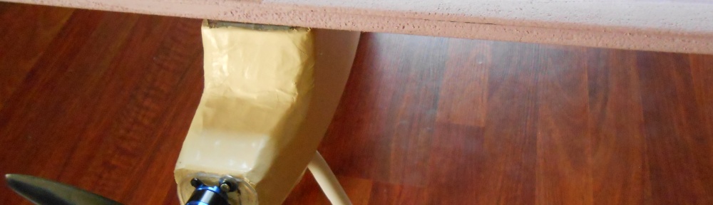
Note: the wires of the motor simply dangle down the underside of the fuselage where they are connected to the esc. You can cover this in some way if you wish.
Brushless Motor
Radio:
Read the manual. People all over the internet use the cheap 2.4ghz radio systems. Know your radio and its functions, so you don’t destroy your plane:P
Congratulations, you’ve finished the build. Get out there and start flying!

